Objective: Understand how liquid crystal displays work and how to implement a 7-segment LCD
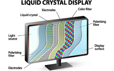
Liquid-crystal displays (LCD) are flat panel displays that utilize the properties of materials called liquid crystals in combination with polarizers to control various pixel. A common set up is shown below. First, light from an LED back plane is fed through a horizontal polarizing film to polarize the incoming light. Secondly the liquid crystals for the pixels that are to be turned on are physically twisted which rotates the light by 90 degrees this filtered light goes through a red, green, or blue color filter. Lastly the light goes through a vertical polarizing filter which blocks all light from the non-twisted pixels.
LCD displays have quickly emerged as the most widely used display technology, making up most of the phone, computer, and television displays currently on the market. In this lab we will be implementing a 2 digit counter using a twisted nematic (TN) 7-segment LCD display.
LCD displays have quickly emerged as the most widely used display technology, making up most of the phone, computer, and television displays currently on the market. In this lab we will be implementing a 2 digit counter using a twisted nematic (TN) 7-segment LCD display.
How an LCD works
|

LCDs have become ubiquitous in society. As LCDs are cheaper to manufacture and are not as suseptible to age degradation, LCDs are the go to display in many applications
|

Polarized microphotograph of unaligned nematic liquid crystal. Image from Ji-Hoon Lee of the Case Liquid Crystal and Complex Fluids Group
Lab Components
- One 3 digit TN 7-segment display Datasheet (https://www.lumex.com/spec/LCD-S2X1C50TR.pdf)
- Resistors (2*10kΩ)
- Push-button Switch (x2)
- Solder-less Protoboard
- Jumper Wires
- Arduino Leonardo
Part 1: The 7-Segment Display
In part 1 of the lab we will write a program that will count from 0 to 100 on the LCD.
Procedure:
- Write a simple program in Arduino IDE that counts incrementally from 0 to 100 on the 3-digit LCD. Choose an acceptable refresh rate (Note: The arduino allows you to configure the analog pins as digital outputs.)
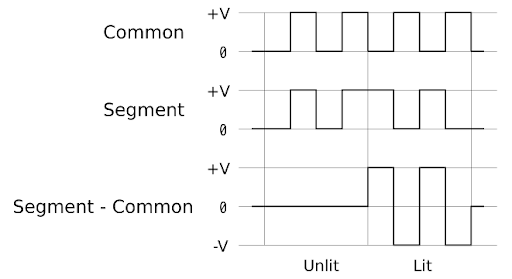
- It is important to note that the display must be driven using an AC waveform. Apply DC voltage to the display will cause degradation
- It is important to note that since we are applying AC voltages on each of the pins. The applied voltage of each segment is Vsegment - Vcom. The figure below illustrates how to turn on a segment.
- Save a video of the display in action along with any relevant code.
Part 2: A Simple Calculator
In part two of the lab we will be using two push-button switches to implement a simple calculator. Using the buttons to select numbers on the display, the calculator should be able to add two numbers whose sum is less than or equal to 100 and be able to deal with the overflow.
Procedure:
- Write a simple program in Arduino IDE that creates a simple two number adder. Using the push-buttons to select numbers on the display, the calculator should be able to add two numbers whose sum is less than or equal to 100 and be able to deal with the overflow. (A good guide for implementing the buttons https://www.arduino.cc/en/tutorial/button)
- It is important to note that the display must be driven using an AC waveform. Apply DC voltage to the display will cause degradation.
- The buttons may be implemented in any creative way as long as addends are displayed on the LCD along with the final sum.
- Save a video of the display in action along with any relevant code.
Questions:
- What frequency did you drive your LCD at? How did you choose this frequency?
- The current 3 digit 7-segment display required 16 unique digital lines. What are some techniques we can use to minimize the complexity for large-scale designs
- What are the pros of LCD technology? what are the cons?